前言 本项目是一个用于学习图形学的软渲染器项目,基于C++和Rider编写,实现了仿照OpenGL风格的,简单但完整的渲染管线流程
光栅化 直线绘制 软渲染器开发要解决的第一个问题就是:给定两个点A和B,如何用画点的API来画这两个点连成的线?
比较容易想到的是,从0按照给定的步长迭代到1,根据步长为权重Lerp两个点的xy
1
2
3
4
5
for (float t=0. ; t<1. ; t+=.01 ) { int x = x0 + (x1-x0)*t; int y = y0 + (y1-y0)*t; image.set (x, y, color); }
或者是从Ax迭代到Bx,根据每次迭代的步长比例Lerp出当前的y值
1
2
3
4
5
for (int x = x0; x <= x1; x++) { float t = (x - x0) / (float )(x1 - x0); int y = y0 * (1. - t) + y1 * t; image.set (x, y, color); }
然而以上两者都涉及到浮点数运算,每帧渲染过程中的大量调用会导致性能开销过大
相比之下,Brensenham算法运算过程中只涉及到整数加减乘法,整体就高效了很多
考虑到篇幅,接下来不会涉及到具体的Brensenham算法推导,只简单介绍下思路,有兴趣的可自行搜索
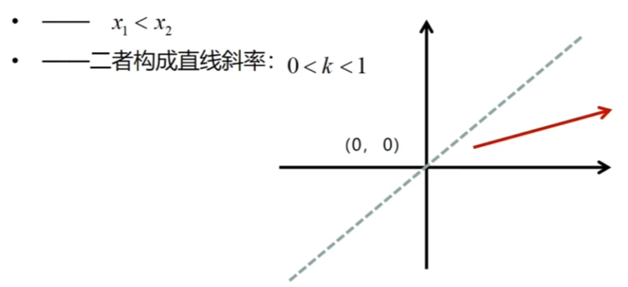
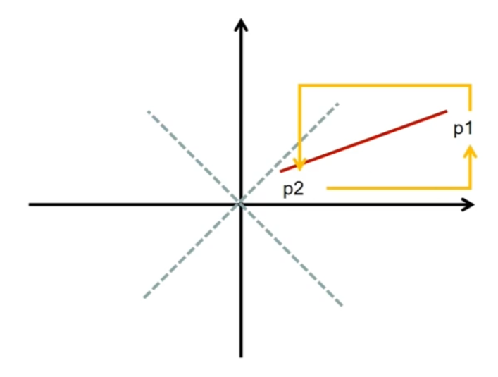
首先从最简单的情况来看,目标直线从左下往右上,且x轴上的长度>=y轴上的长度
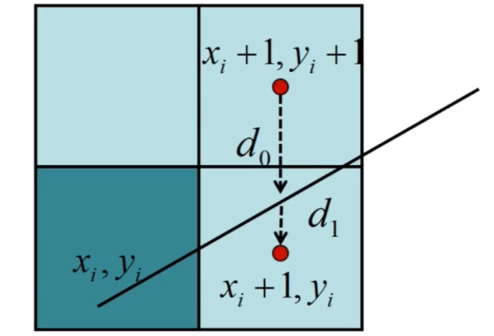
我们先沿着x轴进行步进,每次步进时来决策往上走还是保持直行,而决策依据就是离上面的像素距离近,还是离当前的像素距离近,即d0和d1的比较
对于其他情况来说,只要想办法让它转换为最简单的情况再进行绘制就行
比如:
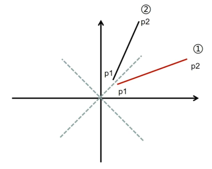
x轴上的长度<y轴上的长度时,将两个点的xy互换得到镜像即可
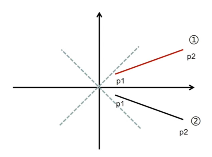
直线是从左上到右下时,将两个点的y值取反即可
而下面这种两个点反过来的情况更简单,直接把要绘制的起点和终点交换就行
综合以上三种操作即可将任意情况的直线转换为最简单的情况
需要注意的是如果有进行过交换xy和y值取反,就需要在实际绘制时再反向操作回来 ,保证绘制结果的正确
下面是具体代码:
1
2
3
4
5
6
7
8
9
10
11
12
13
14
15
16
17
18
19
20
21
22
23
24
25
26
27
28
29
30
31
32
33
34
35
36
37
38
39
40
41
42
43
44
45
46
47
48
49
50
51
52
53
54
55
56
57
58
59
60
61
62
63
64
65
66
67
68
69
70
71
72
73
74
75
76
77
78
void Raster::RasterizeLine (std::vector<Point>& results, const Point& p1, const Point& p2) Point start = p1; Point end = p2; if (start.X > end.X) { std::swap (start, end); } results.push_back (start); bool isFlipY = false ; if (start.Y > end.Y) { start.Y *= -1.0f ; end.Y *= -1.0f ; isFlipY = true ; } int deltaX = end.X - start.X; int deltaY = end.Y - start.Y; bool isSwapXY = false ; if (deltaX < deltaY) { std::swap (start.X, start.Y); std::swap (end.X, end.Y); std::swap (deltaX, deltaY); isSwapXY = true ; } int currentX = start.X; int currentY = start.Y; int resultX = 0 ; int resultY = 0 ; int p = 2 * deltaY - deltaX; for (int i = 0 ; i < deltaX; ++i) { if (p >= 0 ) { currentY += 1 ; p -= 2 * deltaX; } currentX += 1 ; p += 2 * deltaY; resultX = currentX; resultY = currentY; if (isSwapXY) { std::swap (resultX, resultY); } if (isFlipY) { resultY *= -1 ; } Point currentPoint; currentPoint.X = resultX; currentPoint.Y = resultY; InterpolantLine (start, end, currentPoint); results.push_back (currentPoint); } }
直线颜色插值 成功绘制出直线后,要考虑的下一个问题就是如何让直线呈现出均匀变化的颜色,这就需要对直线上的像素进行颜色插值
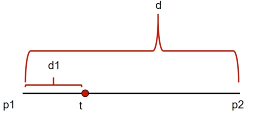
在计算直线的颜色插值时,能够直接想到使用当前点离起点的距离作为权重进行颜色Lerp,不过因为涉及到距离计算会造成比较大的性能开销
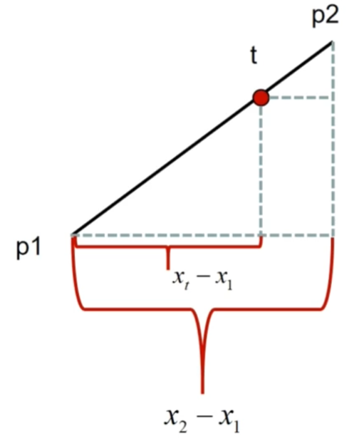
因此我们选择另一个方法,根据x轴上的比例作为权重进行Lerp,需要注意的是如果两个点x轴位置重合(这意味着会除以0),就需要选择y轴来计算
具体代码如下:
1
2
3
4
5
6
7
8
9
10
11
12
13
14
15
16
void Raster::InterpolantLine (const Point& p1, const Point& p2, Point& target) float weight = 1.0f ; if (p1.X != p2.X) { weight = static_cast <float >(target.X - p1.X) / static_cast <float >(p2.X - p1.X); } else if (p1.Y != p2.Y) { weight = static_cast <float >(target.Y - p1.Y) / static_cast <float >(p2.Y - p1.Y); } target.Color = LerpRGBA (p1.Color, p2.Color, weight); }
三角形光栅化 给定一个三角形,如何找出这个三角形覆盖的所有像素?
总的来说就是2个步骤:
找到三角形的最小包围盒范围
遍历包围盒内的像素,判断此像素是否在三角形内
步骤1很简单,通过对比3个顶点,使用它们中最小的xy和最大的xy就可以构造出最小包围盒
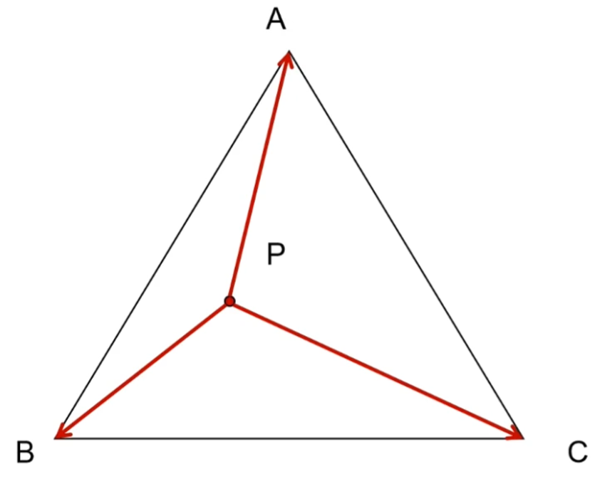
步骤2稍微有点麻烦,需要先计算出从当前点P分别到三角形3个顶点的向量PA、PB、PC,然后两两叉乘(PAxPB,PBxPC,PCxPA),借助叉乘的性质(叉乘双方的方向不同时,叉乘结果符号相反)可知,如果3个叉乘结果是同号的,那么点P就再三角形中,否则在外面
具体代码如下:
1
2
3
4
5
6
7
8
9
10
11
12
13
14
15
16
17
18
19
20
21
22
23
24
25
26
27
28
29
30
31
32
33
34
35
36
37
38
39
void Raster::RasterizeTriangle (std::vector<Point>& results, const Point& p1, const Point& p2, const Point& p3) const int maxX = std::max (p1.X, std::max (p2.X, p3.X)); const int minX = std::min (p1.X, std::min (p2.X, p3.X)); const int maxY = std::max (p1.Y, std::max (p2.Y, p3.Y)); const int minY = std::min (p1.Y, std::min (p2.Y, p3.Y)); math::vec2f p1v, p2v, p3v; Point result; for (int i = minX; i <= maxX; ++i) { for (int j = minY; j <= maxY; ++j) { p1v = math::vec2f (p1.X - i, p1.Y - j); p2v = math::vec2f (p2.X - i, p2.Y - j); p3v = math::vec2f (p3.X - i, p3.Y - j); const auto cross1 = math::cross (p1v, p2v); const auto cross2 = math::cross (p2v, p3v); const auto cross3 = math::cross (p3v, p1v); const bool negativeAll = cross1 <= 0 && cross2 <= 0 && cross3 <= 0 ; const bool positiveAll = cross1 >= 0 && cross2 >= 0 && cross3 >= 0 ; if (negativeAll || positiveAll) { result.X = i; result.Y = j; InterpolantTriangle (p1, p2, p3, result); results.push_back (result); } } } }
三角形重心插值 在完成三角形光栅化后,同样要考虑如何对三角形内的像素颜色(及其他属性)进行插值?
这里将采用的方法是三角形重心插值算法,同样的,具体推导过程省略,只简述下思想
计算出从当前点P到分别三角形3个顶点的向量PA、PB、PC,以将原本的三角形分割为三个子三角形,然后根据子三角形的面积对原本三角形面积的占比来决定3个顶点在Lerp时的权重
具体代码如下:
1
2
3
4
5
6
7
8
9
10
11
12
13
14
15
16
17
18
19
20
21
22
23
24
25
26
void Raster::InterpolantTriangle (const Point& p1, const Point& p2, const Point& p3, Point& target) const auto e1 = math::vec2f (p2.X - p1.X, p2.Y - p1.Y); const auto e2 = math::vec2f (p3.X - p1.X, p3.Y - p1.Y); const float sumArea = std::abs (math::cross (e1, e2)); const auto pv1 = math::vec2f (p1.X - target.X, p1.Y - target.Y); const auto pv2 = math::vec2f (p2.X - target.X, p2.Y - target.Y); const auto pv3 = math::vec2f (p3.X - target.X, p3.Y - target.Y); const float v1Area = std::abs (math::cross (pv2, pv3)); const float v2Area = std::abs (math::cross (pv1, pv3)); const float v3Area = std::abs (math::cross (pv1, pv2)); const float weight1 = v1Area / sumArea; const float weight2 = v2Area / sumArea; const float weight3 = v3Area / sumArea; target.Color = LerpRGBA (p1.Color, p2.Color, p3.Color, weight1, weight2, weight3); target.UV = LerpUV (p1.UV,p2.UV,p3.UV,weight1, weight2, weight3); }
图片与UV 想把图片绘制到屏幕上,要做的便是纹理采样
由于绘制的目标区域和图片的大小往往是不一致的,所以需要有一个基于百分比的坐标体系,告诉我们当前屏幕像素要采样到图片上哪一个位置的颜色,这就是UV坐标,图片左下角的UV坐标为(0,0),右上角为(1,1)
这样只需要根据当前像素上的UV,就可以计算出要采样的目标点位置了,比如当前像素的UV为(0.5,0.5),图片宽高为(800,600),那么当前像素要采样的就是图片上(400,300)位置处的颜色
那么问题就来了,如何得出像素的UV?
只需要在光栅化时对顶点UV进行插值即可(暂不考虑透视修正)
最近点采样 在通过UV计算采样目标点位置时,可能会得出一个有小数的结果,这时候要怎么处理呢?
直接使用四舍五入的,就是最近点采样算法
具体代码如下:
1
2
3
4
5
6
7
8
9
10
11
12
13
RGBA GPU::SampleNearest (const math::vec2f& uv) const auto myUV = uv; CheckWrap (myUV.x); CheckWrap (myUV.y); int x = std::round (myUV.x * (image->Width - 1 )); int y = std::round (myUV.y * (image->Height - 1 )); const int position = image->Width * y + x; return image->Data[position]; }
最近点采样算法的问题是,如果图片的分辨率较小,就会出现明显的颗粒感,因为图片像素不够会导致多个屏幕像素共用临近的同一个图片像素上色,导致过度不够平滑
要解决这个问题,需要在图片像素不足时,计算出新的图片像素给到屏幕像素,双线性插值就是这样的方法
双线性插值 顾名思义,双线性插值会进行两次线性插值,即在目标位置选择周围的4个图片像素进行插值
首先是对0和2,1和3插值出left和right,然后再对left和right插值出目标的图片像素颜色
具体代码如下:
1
2
3
4
5
6
7
8
9
10
11
12
13
14
15
16
17
18
19
20
21
22
23
24
25
26
27
28
29
30
31
32
33
34
35
36
37
38
39
40
41
42
43
44
45
46
47
RGBA GPU::SampleBilinear (const math::vec2f& uv) const auto myUV = uv; CheckWrap (myUV.x); CheckWrap (myUV.y); const float x = myUV.x * static_cast <float >(image->Width - 1 ); const float y = myUV.y * static_cast <float >(image->Height - 1 ); const int left = std::floor (x); const int right = std::ceil (x); const int bottom = std::floor (y); const int top = std::ceil (y); const int posLeftTop = image->Width * top + left; const int posLeftBottom = image->Width * bottom + left; const int posRightTop = image->Width * top + left; const int posRightBottom = image->Width * bottom + right; float yScale; if (top == bottom) { yScale = 1 ; } else { yScale = (y - static_cast <float >(bottom)) / static_cast <float >(top - bottom); } const auto leftColor = Raster::LerpRGBA (image->Data[posLeftBottom], image->Data[posLeftTop], yScale); const auto rightColor = Raster::LerpRGBA (image->Data[posRightBottom], image->Data[posRightTop], yScale); float xScale; if (left == right) { xScale = 1 ; } else { xScale = (x - static_cast <float >(left)) / static_cast <float >(right - left); } const RGBA resultColor = Raster::LerpRGBA (leftColor, rightColor, xScale); return resultColor; }
纹理Wrap UV坐标一般都是在0-1范围内,而对于不在这个范围里的UV该如何进行采样,就决定了纹理的Wrap模式
两种常见的Wrap模式:
Repeat
Mirror
Repeat模式会对超出范围的UV进行重复采样,形成图片被不断重复出来的样子,计算方法为:如果当前UV为正数,直接取小数部分作为新UV,否则再加上1
Mirror模式则是会生成左右上下都对称的镜像图片,计算方法为:用1减去Repeat算法的结果
渲染管线开始前的准备 基本数据结构 在渲染管线的整体设计上是类似于OpenGL那样的状态机式的,通过绑定VBO、EBO、VAO的ID,然后调用对应接口进行操作,最后调用Draw函数进行渲染
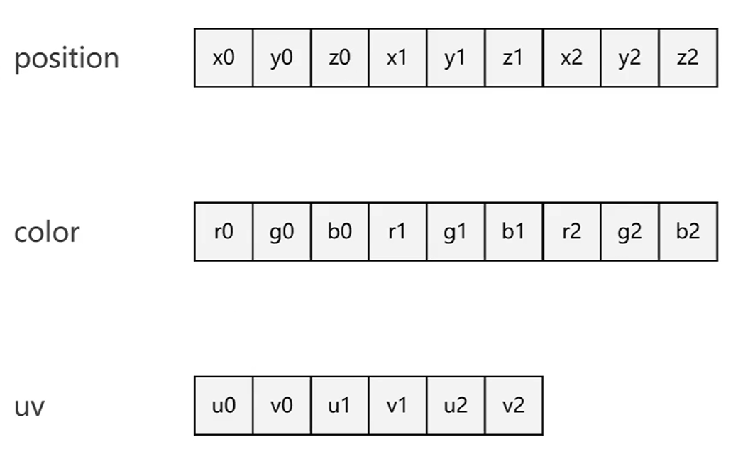
VertexBufferObject(VBO) 对于顶点的数据(如位置,颜色,UV),有两种存储方式
1.分别存放到不同的数组内存空间(分布式)
2.存放到同一个数组内存空间(交叉式)
这些数组内存空间就被称为VBO
ElementBufferObject(EBO) EBO用来存储顶点索引,在本项目中,EBO和VBO都使用同一个类BufferObject来表示:
1
2
3
4
5
6
7
8
9
10
11
12
13
14
15
16
class BufferObject { public : ~BufferObject (); BufferObject (); BufferObject (const BufferObject&) = delete ; void SetBufferData (size_t dataSize, const void * data) byte* GetBuffer () const ; private : size_t bufferSize{0 }; byte* buffer{nullptr }; };
VertexArrayObject(VAO) 那么GPU又是如何知道VBO中数据的读取方式呢?
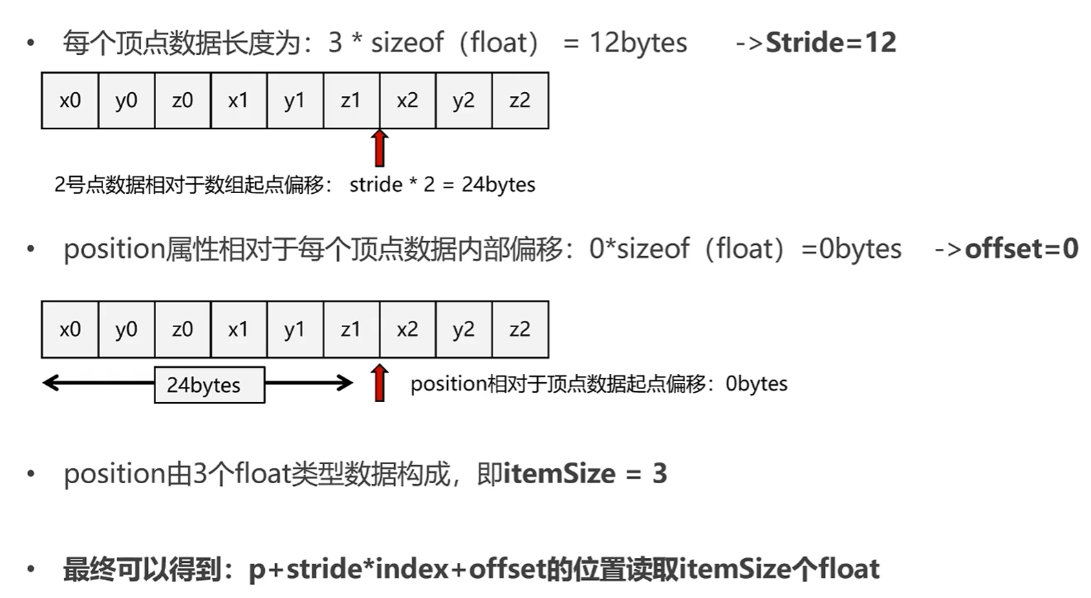
对于两种存储方式,都可以统一用p + stride * index + offset来计算数据读取的起点
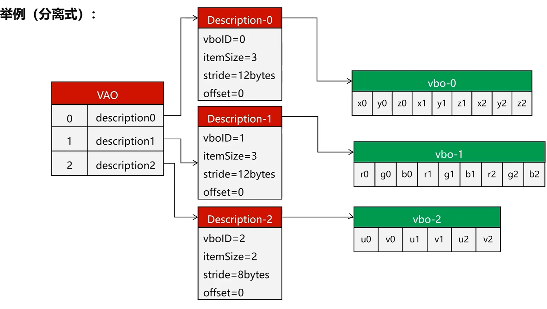
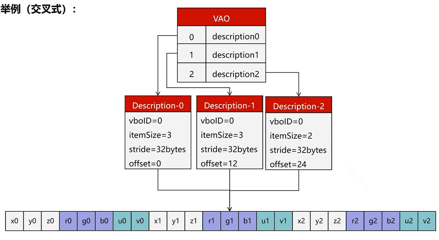
其中p为VBO数组起点,stride为属性跨度(分布式VBO为单个属性的字节大小,交叉式VBO为单个顶点数据的字节大小),index为顶点索引,offset为属性相对偏移(分布式VBO的offset为0)
这些描述数据共同组成了一个结构体
1 2 3 4 5 6 7 8 9 10 11 struct BindingDescription { uint32_t VboId{0 }; size_t ItemSize{0 }; size_t Stride{0 }; size_t Offset{0 }; };
用于保存这些描述数据的就是VAO
1
2
3
4
5
6
7
8
9
10
11
12
13
14
class VertexArrayObject { public : VertexArrayObject () = default ; ~VertexArrayObject () = default ; void Set (uint32_t binding,uint32_t vboID,uint32_t itemSize,uint32_t stride,uint32_t offset) std::map<uint32_t ,BindingDescription> GetBindingMap () const ; void Print () const private : std::map<uint32_t ,BindingDescription> bindingMap; };
举例来说,分布式的VBO和VAO存储结构如下:
交叉式如下:
具体的使用方式:以Mesh类为例 默认使用的是交叉式VBO
1 2 3 4 5 6 7 8 9 10 11 12 13 14 15 16 17 18 19 20 21 22 23 24 25 26 27 28 29 30 31 32 33 34 35 Mesh::Mesh (const std::vector<Vertex>& vertices, const std::vector<unsigned >& indices, uint32_t diffuseTexture, const math::mat4f& localMatrix) { this ->localMatrix = localMatrix; texture = diffuseTexture; if (vertices.empty () || indices.empty ()) { return ; } vao = gpu->GenVertexArray (); vbo = gpu->GenBuffer (); ebo = gpu->GenBuffer (); gpu->BindBuffer (ARRAY_BUFFER,vbo); gpu->BufferData (ARRAY_BUFFER,vertices.size () * sizeof void *) &vertices[0 ]); gpu->BindBuffer (ELEMENT_ARRAY_BUFFER,ebo); gpu->BufferData (ELEMENT_ARRAY_BUFFER,indices.size () * sizeof uint32_t ),(void *) &indices[0 ]); indicesCount = indices.size (); gpu->BindVertexArray (vao); gpu->VertexAttributePointer (0 ,3 ,sizeof 0 ); gpu->VertexAttributePointer (1 ,3 ,sizeof sizeof float ) * 3 ); gpu->VertexAttributePointer (2 ,2 ,sizeof sizeof float ) * 6 ); gpu->BindBuffer (ARRAY_BUFFER,0 ); gpu->BindBuffer (ELEMENT_ARRAY_BUFFER,0 ); gpu->BindVertexArray (0 ); }
可以看出整个API的设计上都是仿照OpenGL的
总的来说,就是通过生成接口获取到对应ID,然后使用绑定接口传入ID进行绑定,绑定完成后后续的操作都是针对此ID绑定的对象进行的
绘制调用则是:
1
2
3
4
5
6
7
8
9
10
11
12
13
14
15
16
17
18
19
20
21
22
23
24
25
26
27
void Mesh::Draw (const math::mat4f& preMatrix, LightShader* shader) const const auto modelMatrix = preMatrix * localMatrix; if (vao) { shader->ModelMatrix = modelMatrix; if (texture) { shader->DiffuseTexture = texture; } gpu->BindVertexArray (vao); gpu->BindBuffer (ELEMENT_ARRAY_BUFFER,ebo); gpu->DrawElement (DRAW_TRIANGLES,0 ,indicesCount); gpu->BindVertexArray (0 ); gpu->BindBuffer (ELEMENT_ARRAY_BUFFER,0 ); } for (const auto mesh : children) { mesh->Draw (modelMatrix,shader); } }
Shader Shader直接使用C++代码进行编写,定义Shader基类
1
2
3
4
5
6
7
8
9
10
11
12
13
class Shader { public : Shader () = default ; virtual ~Shader () = default ; virtual VSOutput VertexShader (const std::map<uint32_t , BindingDescription>& bindingMap, const std::map<uint32_t , BufferObject*>& bufferMap, const uint32_t & index) 0 ; virtual void FragmentShader (const VSOutput& input, FSOutput& output, const std::map<uint32_t , Texture*>& textures) 0 ; };
主要为顶点Shader和片元Shader定义出对应的抽象方法
然后Shader需要的数据(Uniforms)又在各个实现类中定义,如DefaultShader:
1
2
3
4
5
6
7
8
9
10
11
12
13
14
15
16
class DefaultShader :public Shader{ public : DefaultShader () = default ; ~DefaultShader () override = default ; public : math::mat4f ModelMatrix; math::mat4f ViewMatrix; math::mat4f ProjectionMatrix; VSOutput VertexShader (const std::map<uint32_t , BindingDescription>& bindingMap, const std::map<uint32_t , BufferObject*>& bufferMap, const uint32_t & index) override void FragmentShader (const VSOutput& input, FSOutput& output, const std::map<uint32_t , Texture*>& textures) override };
DefaultShader做的事情很简单,在顶点Shader中通过MVP矩阵将顶点位置转换到剪裁空间,在片元Shader中为片元赋值颜色值
1
2
3
4
5
6
7
8
9
10
11
12
13
14
15
16
17
18
19
20
21
22
23
24
25
VSOutput DefaultShader::VertexShader (const std::map<uint32_t , BindingDescription>& bindingMap, const std::map<uint32_t , BufferObject*>& bufferMap, const uint32_t & index) auto pos = GetVector (bindingMap,bufferMap,0 ,index); pos.w = 1.0f ; const auto color = GetVector (bindingMap,bufferMap,1 ,index); const math::vec2f uv = GetVector (bindingMap,bufferMap,2 ,index); VSOutput output; output.Position = ProjectionMatrix * ViewMatrix * ModelMatrix * pos; output.Color = color; output.UV = uv; return output; } void DefaultShader::FragmentShader (const VSOutput& input, FSOutput& output, const std::map<uint32_t , Texture*>& textures) output.PixelPos.x = static_cast <int >(input.Position.x); output.PixelPos.y = static_cast <int >(input.Position.y); output.Depth = input.Position.z; output.Color = VectorToRGBA (input.Color); }
摄像机 摄像机移动和旋转的本质就是通过读取玩家操作来修正ViewMatrix的过程
首先是通过读取鼠标移动来改变当前摄像机的前方向front变量:
1
2
3
4
5
6
7
8
9
10
11
12
13
void Camera::OnMouseMove (const int & x, const int & y) if (mouseMoving) { const int xOffset = x - currentMouseX; const int yOffset = y - currentMouseY; currentMouseX = x; currentMouseY = y; SetPitch (-yOffset); SetYaw (xOffset); } }
1
2
3
4
5
6
7
8
9
10
11
12
13
14
15
16
17
18
19
20
21
22
23
24
25
26
27
28
29
30
31
void Camera::SetPitch(int yOffset){ pitch += yOffset * sensitivity; if (pitch >= 89.0f ) { pitch = 89.0f ; } if (pitch <= -89.0f ) { pitch = -89.0f ; } front.y = sin(DEG2RAD(pitch)); front.x = cos(DEG2RAD(yaw)) * cos(DEG2RAD(pitch)); front.z = sin(DEG2RAD(yaw)) * cos(DEG2RAD(pitch)); front = math::normalize(front); } void Camera::SetYaw(int xOffset){ yaw += xOffset * sensitivity; front.y = sin(DEG2RAD(pitch)); front.x = cos(DEG2RAD(yaw)) * cos(DEG2RAD(pitch)); front.z = sin(DEG2RAD(yaw)) * cos(DEG2RAD(pitch)); front = math::normalize(front); }
然后通过读取方向按键,将各个方向进行汇总得到最终的移动方向,最后乘以速度来得到最终位置,从而计算出当前的ViewMatrix
1
2
3
4
5
6
7
8
9
10
11
12
13
14
15
16
17
18
19
20
21
22
23
24
25
26
27
28
29
30
void Camera::Update () math::vec3f moveDir = {0 ,0 ,0 }; const math::vec3f right = math::normalize (math::cross (front,top)); if (moveState & MOVE_FRONT) { moveDir += front; } if (moveState & MOVE_BACK) { moveDir += -front; } if (moveState & MOVE_LEFT) { moveDir += -right; } if (moveState & MOVE_RIGHT) { moveDir += right; } if (math::lengthSquared (moveDir) != 0 ) { moveDir = math::normalize (moveDir); position += speed * moveDir; } viewMatrix = math::lookAt<float >(position,position + front,top); }
渲染管线各阶段 模型读取 使用开源库Assimp读取模型,并按照父子节点的关系来组织Mesh
处理Mesh节点的代码如下:
1
2
3
4
5
6
7
8
9
10
11
12
13
14
15
16
17
18
19
20
21
22
23
24
void Model::ProcessNode (Mesh* parent, const aiNode* aiNode, const aiScene* scene) const auto node = new Mesh ({},{},0 ,math::mat4f ()); parent->AddChild (node); node->localMatrix = GetMat4f (aiNode->mTransformation); for (unsigned int i = 0 ; i < aiNode->mNumMeshes; ++i) { const unsigned meshIndex = aiNode->mMeshes[i]; aiMesh* aiMesh = scene->mMeshes[meshIndex]; auto mesh = ProcessMesh (aiMesh,scene); meshes.push_back (mesh); node->AddChild (mesh); } for (unsigned int i = 0 ; i < aiNode->mNumChildren; ++i) { ProcessNode (node,aiNode->mChildren[i],scene); } }
这里将模型变换存储在自身的LocalMatrix里,将具体顶点数据存储于子节点中
Mesh在绘制时给Shader使用的ModelMatrix就是用自身的LocalMatrix乘以从父节点累积下来的ModelMatrix ,并在绘制子节点时将ModelMatix往下传递
顶点Shader 此阶段会按照输入索引的顺序处理所有顶点,至少保证将顶点位置转换到了剪裁空间,并将结果放入VSOutput中
1
2
3
4
5
6
std::vector<VSOutput> vsOutputs{}; VertexShaderStage (vsOutputs, vao, ebo, first, count);if (vsOutputs.empty ()){ return ; }
1
2
3
4
5
6
7
8
9
10
11
12
13
14
15
16
17
18
void GPU::VertexShaderStage (std::vector<VSOutput>& vsOutputs, const VertexArrayObject* vao, const BufferObject* ebo, const uint32_t first, const uint32_t count) const const auto bindingMap = vao->GetBindingMap (); const byte* indicesData = ebo->GetBuffer (); uint32_t index = 0 ; for (uint32_t i = first; i < first + count; ++i) { const size_t indicesOffset = i * sizeof uint32_t ); memcpy (&index, indicesData + indicesOffset, sizeof uint32_t )); VSOutput output = shader->VertexShader (bindingMap, bufferMap, index); vsOutputs.push_back (output); } }
多边形剪裁 此阶段会对视野外的顶点进行剪裁,然后重新生成新的顶点和三角形
1
2
3
4
5
6
7
std::vector<VSOutput> clipOutputs{}; Clipper::DoClipSpace (drawMode, vsOutputs, clipOutputs); vsOutputs.clear (); if (clipOutputs.empty ()){ return ; }
Sutherland-Hodgman算法 剪裁算法使用了Sutherland-Hodgman算法,也叫逐边剪裁算法
以二维平面为例,每次检查一条边,然后使用当前点P和上一个点S进行测试,有4种可能的结果:
会根据结果产生一个新的点集数组,简单的说就是有交点I就输出I,P在内侧就输出P
然后使用新的结果点集数组对下一条边进行测试,周而复始直到测试完所有的边
应用到三维空间,就是把逐边换成了逐平面,具体代码:
1
2
3
4
5
6
7
8
9
10
11
12
13
14
15
16
17
18
19
20
21
22
23
24
25
26
27
28
29
30
31
32
33
34
35
36
37
38
39
40
41
42
43
44
45
46
47
48
49
50
51
52
53
54
55
56
57
58
59
60
61
62
63
64
65
66
67
68
69
70
71
72
73
74
75
76
77
78
79
80
81
82
83
84
85
86
87
88
89
void Clipper::SutherlandHodgman (const uint32_t & drawMode, const std::vector<VSOutput>& primitives, std::vector<VSOutput>& outputs) assert (outputs.empty ()); const std::vector<math::vec4f> clipPlanes = { math::vec4f (0.0f , 0.0f , 0.0f , 1.0f ), math::vec4f (0.0f , 0.0f , 1.0f , 1.0f ), math::vec4f (0.0f , 0.0f , -1.0f , 1.0f ), math::vec4f (1.0f , 0.0f , 0.0f , 1.0f ), math::vec4f (-1.0f , 0.0f , 0.0f , 1.0f ), math::vec4f (0.0f , -1.0f , 0.0f , 1.0f ), math::vec4f (0.0f , 1.0f , 0.0f , 1.0f ) }; outputs = primitives; std::vector<VSOutput> inputs; for (uint32_t i = 0 ; i < clipPlanes.size (); ++i) { inputs = outputs; outputs.clear (); auto plane = clipPlanes[i]; for (uint32_t index = 0 ; index < inputs.size (); ++index) { const auto lastIndex = (index + inputs.size () - 1 ) % inputs.size (); auto current = inputs[index]; auto last = inputs[lastIndex]; if (inside (current.Position, plane)) { if (drawMode != DRAW_LINES || index != inputs.size () - 1 ) { if (!inside (last.Position, plane)) { auto intersectPoint = Intersect (last, current, plane); outputs.push_back (intersectPoint); } } outputs.push_back (current); } else { if (drawMode != DRAW_LINES || index != inputs.size () - 1 ) { if (inside (last.Position, plane)) { auto intersectPoint = Intersect (last, current, plane); outputs.push_back (intersectPoint); } } } } } }
判断点是否在平面内,具体推导就略过了:
1
2
3
4
bool Clipper::inside (const math::vec4f& point, const math::vec4f& plane) return dot (point,plane) >= 0 ; }
交点I的属性插值,计算S到P的距离,然后用S到平面的距离来计算插值权重:
1
2
3
4
5
6
7
8
9
10
11
12
13
VSOutput Clipper::Intersect (const VSOutput& last, const VSOutput& current, const math::vec4f& plane) const float distanceLast = math::dot (last.Position, plane); const float distanceCurrent = math::dot (current.Position, plane); const float weight = distanceLast / (distanceLast - distanceCurrent); VSOutput output; output.Position = math::lerp (last.Position, current.Position, weight); output.Color = math::lerp (last.Color, current.Color, weight); output.Normal = math::lerp (last.Normal, current.Normal, weight); output.UV = math::lerp (last.UV, current.UV, weight); return output; }
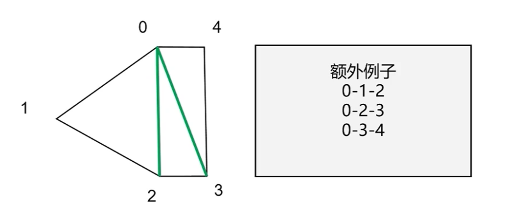
三角形重建 在得到最终剪裁结果后需要进行是三角形重建,具体方法为:
固定使用0号点为三角形第1个顶点,然后2个一组来作为剩下的2个顶点
1
2
3
4
5
6
for (uint32_t c = 0 ; c < result.size () - 2 ; ++c){ outputs.push_back (result[0 ]); outputs.push_back (result[c + 1 ]); outputs.push_back (result[c + 2 ]); }
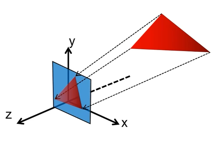
透视除法 此阶段将顶点从裁剪空间转换到NDC空间
1
2
3
4
for (auto & output : clipOutputs){ PerspectiveDivision (output); }
1
2
3
4
5
6
7
8
9
10
11
12
13
14
15
16
17
18
void GPU::PerspectiveDivision (VSOutput& vsOutput) vsOutput.OneOverW = 1.0f / vsOutput.Position.w; vsOutput.Position *= vsOutput.OneOverW; vsOutput.Position.w = 1 ; vsOutput.Color *= vsOutput.OneOverW; vsOutput.Normal *= vsOutput.OneOverW; vsOutput.UV *= vsOutput.OneOverW; Trim (vsOutput); }
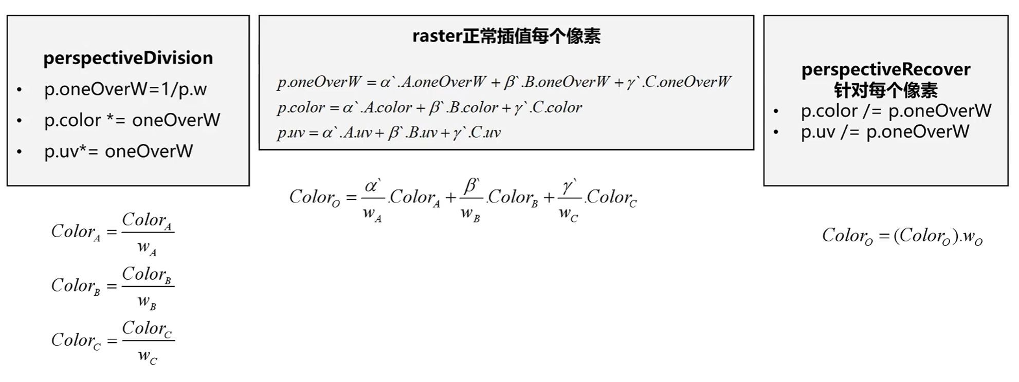
需要注意的是,在透视投影后,于屏幕空间进行的三角形重心插值比例相对于三维空间下的三角形是不准确的
需要在光栅化后进行额外的透视修正,修正方法为:
具体推导此处略过
背面剔除 此阶段会剔除掉具体的三角形,首先要提前设定好何种方向排列的顶点为正面,然后设定要剔除哪一面的三角形
1
2
3
4
5
6
7
8
9
10
11
12
13
14
std::vector<VSOutput> cullOutputs = clipOutputs; if (drawMode == DRAW_TRIANGLES && enableCullFace){ cullOutputs.clear (); for (uint32_t i = 0 ; i < clipOutputs.size () - 2 ; i += 3 ) { if (Clipper::CullFace (frontFace, cullFace, clipOutputs[i], clipOutputs[i + 1 ], clipOutputs[i + 2 ])) { const auto start = clipOutputs.begin () + i; const auto end = clipOutputs.begin () + i + 3 ; cullOutputs.insert (cullOutputs.end (), start, end); } } }
NDC空间下为左手坐标系,叉乘结果的z>0就说明是逆时针排列
1
2
3
4
5
6
7
8
9
10
11
12
13
14
15
16
17
18
19
20
21
22
23
24
25
26
27
28
29
30
31
32
33
34
35
36
37
38
39
40
41
42
43
44
45
bool Clipper::CullFace (const uint32_t & frontFace, const uint32_t & cullFace, const VSOutput& p1, const VSOutput& p2, const VSOutput& p3) const math::vec3f e1 = p2.Position - p1.Position; const math::vec3f e2 = p3.Position - p1.Position; const math::vec3f normal = math::cross (e1,e2); if (cullFace == BACK_FACE) { if (frontFace == FRONT_FACE_CCW) { return normal.z > 0 ; } else { return normal.z < 0 ; } } else { if (frontFace == FRONT_FACE_CCW) { return normal.z < 0 ; } else { return normal.z > 0 ; } } }
屏幕空间映射 此阶段将顶点从NDC空间映射到屏幕空间
1
2
3
4
for (auto & output : cullOutputs){ ScreenMapping (output); }
1
2
3
4
void GPU::ScreenMapping (VSOutput& vsOutput) vsOutput.Position = screenMatrix * vsOutput.Position; }
光栅化 此阶段会计算出被三角形覆盖的片元有哪些,具体内容已在前一篇章中介绍
1
2
3
4
5
6
std::vector<VSOutput> rasterOutputs; Raster::Rasterize (rasterOutputs, drawMode, cullOutputs); if (rasterOutputs.empty ()) { return ; }
透视恢复 此阶段将修正在屏幕空间进行的三角形重心插值产生的透视误差,具体见透视除法 一节
1
2
3
4
for (auto & output : rasterOutputs){ PerspectiveRecover (output); }
1
2
3
4
5
6
void GPU::PerspectiveRecover (VSOutput& vsOutput) vsOutput.Color /= vsOutput.OneOverW; vsOutput.Normal /= vsOutput.OneOverW; vsOutput.UV /= vsOutput.OneOverW; }
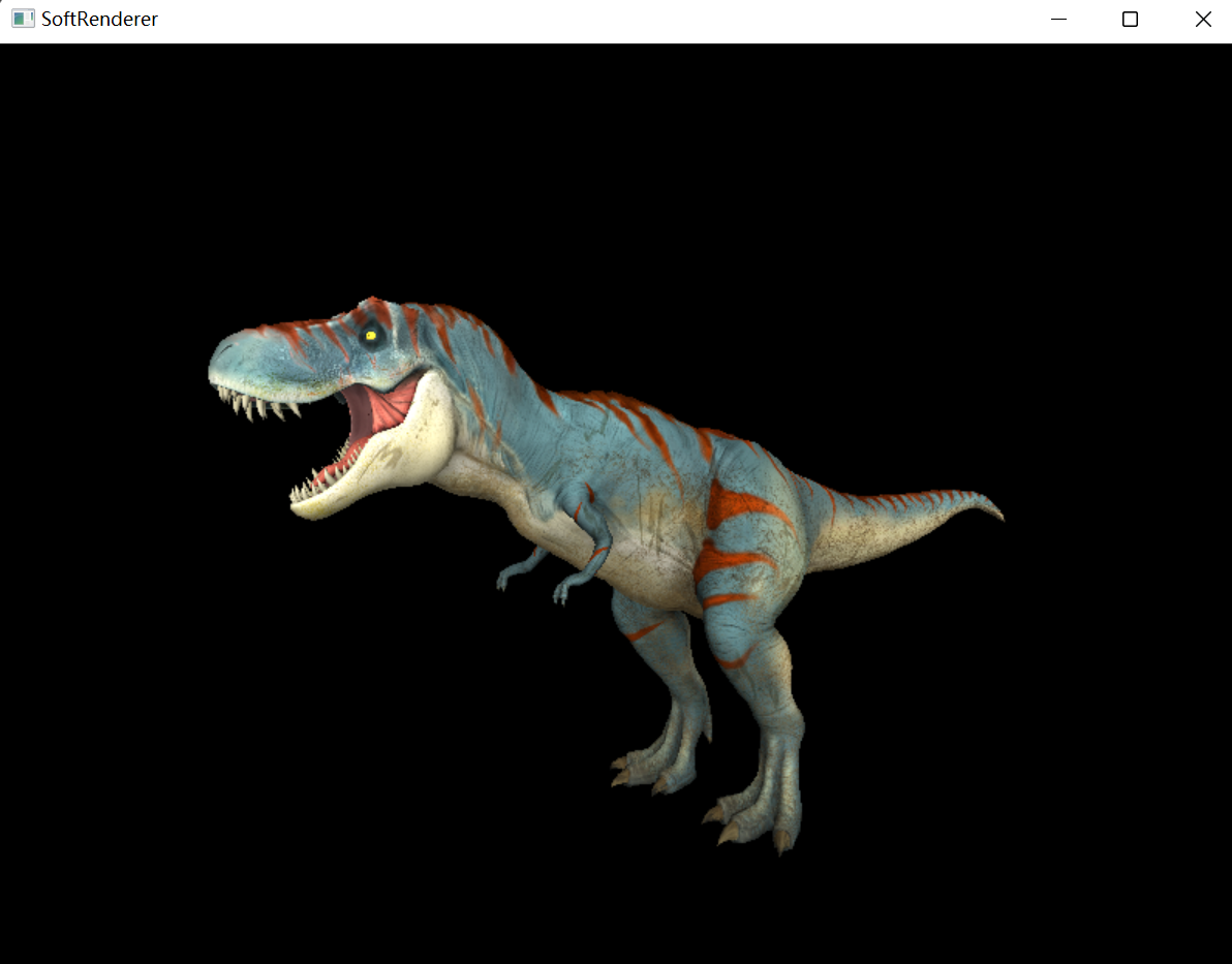
片元Shader 此阶段为光栅化后得到的每个片元计算颜色,在经过各种测试与混合后写入到帧缓存中,最后显示到屏幕上
1
2
3
4
5
6
7
8
9
10
11
12
13
14
15
16
17
18
19
20
21
22
23
24
25
26
27
28
29
30
31
32
33
34
35
36
37
38
FSOutput fsOutput; for (uint32_t i = 0 ; i < rasterOutputs.size (); ++i){ shader->FragmentShader (rasterOutputs[i], fsOutput, textureMap); const uint32_t pixelPos = fsOutput.PixelPos.y * frameBuffer->Width + fsOutput.PixelPos.x; RGBA color = fsOutput.Color; if (color.A == 0 ) { continue ; } if (enableStencilTest) { const bool stencilTestResult = StencilTest (fsOutput); StencilOp (fsOutput,stencilTestResult); if (!stencilTestResult) { continue ; } } if (enableDepthTest && !DepthTest (fsOutput)) { continue ; } if (enableBlending && color.A < 1 ) { color = Blend (fsOutput); } frameBuffer->ColorBuffer[pixelPos] = color; }
